The world of electric motors is vast and varied, with numerous designs tailored for specific applications. Among these, slip ring induction motors hold a unique place due to their versatile capabilities and robust design. This post explores the intricacies of these motors, guiding you through their operation, construction, and real-world applications.
At its core, a slip ring induction motor is an electric motor that utilizes a unique method for introducing resistance into its rotor circuit, enhancing its starting capability and control over speed. The inclusion of slip rings—the eponymous components—marks the defining characteristic that sets these motors apart from their squirrel cage counterparts.
Understanding Slip Ring Induction Motors
To demystify the complex yet fascinating world of slip ring induction motors, an illustrative guide serves as the first step into comprehending their internal workings and unique attributes. The intricate dance of electricity and mechanics hidden within these motors’ casings is best introduced through a detailed diagram, acting as a map to navigate the components that constitute a slip ring induction motor.
Introduction to the Slip Ring Induction Motor Diagram for a Visual Breakdown of the Parts
Visual aids, particularly diagrams, play a pivotal role in the journey of understanding complex machinery. The diagram of a slip ring induction motor acts as a cornerstone for learners and professionals alike, illustrating the placement and role of each component. This visual breakdown embarks from the exterior framework into the heart of the motor, detailing the stator’s coil arrangements, the rotor’s structure, the positioning of the slip rings, and their connections to the rotor circuit. With clarity in presentation, the diagram dissects the motor into understandable parts, enabling a granular look at how each component contributes to the motor’s overall operation. This approach not only simplifies the learning curve but also fosters a deeper appreciation for the engineering marvel that slip ring induction motors represent.
A Look at Why Understanding the Diagram is Crucial for Grasping the Motor’s Functionality
Delving into the mechanics of slip ring induction motors without a fundamental understanding of their constituent parts is akin to navigating unfamiliar terrain without a map. The diagram serves a dual purpose: it not only introduces the motor’s anatomy but also forms the basis for understanding complex concepts such as the interaction between the rotating magnetic field and the rotor. Further drawing attention to the slip rings and brushes setup, the diagram explicitly highlights how these components facilitate the introduction of external resistance into the rotor circuit — a key feature that distinguishes slip ring motors from their counterparts. Understanding this unique relationship is crucial for grasping concepts like torque generation, speed control, and the motor’s overall functionality. Therefore, the diagram is not just a representation of physical components but a foundational tool that bridges theory with application, enabling learners to decode the motor’s operation and appreciate the nuances that underlie its performance. The coherence in transitioning from a visual guide to deepening conceptual understanding underscores the importance of diagrams in educational and professional contexts, especially when exploring the technicalities of slip ring induction motors.
The Key Principles Behind Slip Ring Induction Motors
Slip ring induction motors, developed to enhance the capability and versatility of the induction motor family, operate on core principles that differentiate them from their counterparts. These motors, designed to offer superior control over torque and speed, especially under variable load conditions, utilize a unique configuration of their rotor circuit to achieve these operational advantages.
In-Depth Discussion of the Slip Ring Induction Motor Working Principle
The foundation of the slip ring induction motor’s operation is predicated on the basic principles of electromagnetic induction and the clever manipulation of the rotor’s resistance. When a 3-phase current flows through the stator winding, it generates a rotating magnetic field, a phenomenon that lies at the heart of almost all induction motors. This magnetic field induces a current in the rotor due to the relative motion between the rotating field and the rotor. However, unlike in squirrel cage rotors, the current in a slip ring rotor flows through the rotor windings, which are connected to external resistances through the slip rings and brushes.
By varying these resistances, one can control the current in the rotor circuit. Higher resistance leads to lower current and, consequently, to a change in the motor’s torque and speed characteristics. This adjustable resistance is particularly useful during startup, where very high torque is desirable at low speeds, or in applications requiring speed variation.
How the 3-Phase Slip Ring Induction Motor Operates Differently from Other Motors
The distinction between slip ring induction motors and other types of motors, such as the more common squirrel cage induction motors, lies in the rotor design and the consequent control it affords the operator. In a standard squirrel cage motor, the rotor bars are permanently short-circuited, and hence, it is not possible to alter the rotor’s resistance while it is running. The slip ring motor, with its external resistance capability, offers a distinct operational advantage by allowing for the adjustment of the motor’s performance according to the load requirements.
This unique feature of slip ring motors makes them an ideal choice for heavy-duty applications where the load may not be constant or where a high starting torque is required, such as in cranes, elevators, and conveyors. The ability to start softly or adjust speed by simply altering external resistances ensures these motors can handle a wide array of tasks more efficiently than their fixed resistance counterparts. Furthermore, this operational flexibility mitigates stress on electrical and mechanical components, enhancing the lifespan and reliability of the motor and the driven machinery.
In essence, the primary difference introduced by the 3-phase slip ring induction motor when compared to other motor types is the level of control and adaptability it brings to electrical drive applications. This has broad implications for industrial and manufacturing processes, where operational efficiency, reliability, and control are paramount.
Slip Ring Induction Motor Nuts and Bolts: Construction and Components
Understanding the construction of slip ring induction motors is crucial for appreciating the ingenuity behind their operation and their widespread application in various industries. Delving into the components, such as stators, rotors, and characteristic slip rings, reveals the motor’s innovative design engineered to offer superior control and performance.
Detailed Breakdown of Construction Elements Including Stators, Rotors, and Especially the Slip Rings
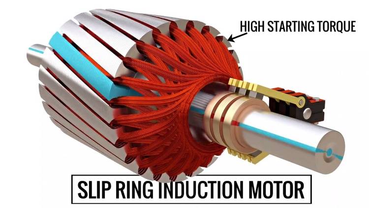
The stator in a slip ring induction motor mirrors that are found in other types of induction motors, comprising a cylindrical frame and core made from laminated silicon steel to minimize eddy current losses. It contains windings laid out in slots, which are connected to a three-phase AC supply. As electrical current courses through these windings, it generates a rotating magnetic field, a foundational aspect of how the motor operates.
At the heart of the motor is the rotor, distinguished by its construction from other motor types by the presence of slip rings. Unlike the squirrel cage rotor, the slip ring rotor is wound similarly to the stator, with end windings extending out and connected to the motor’s external circuitry through slip rings. These slip rings, mounted on the rotor shaft, maintain continuous electrical contact with the stationary brushes, even as the rotor turns. This arrangement facilitates the introduction of external resistance into the rotor circuit, a defining feature that enhances control over the motor’s starting current and torque.
Examining How Each Part Contributes to the Overall Functionality
Each component of the slip ring induction motor interacts harmoniously to achieve the desired operational performance. The stator’s rotating magnetic field induces a current in the rotor, but the magnitude and phase of this current—and consequently, the motor’s torque and speed—can be finely controlled by varying the resistance inserted via the slip rings and brush arrangement. During startup, increasing the resistance helps to limit the starting current and increase the starting torque, allowing for smooth and gradual acceleration. This is particularly beneficial in applications requiring heavy startup loads or precise control over acceleration.
Furthermore, adjusting the resistance during operation allows for control over the motor’s speed, which is invaluable in applications where speed needs to vary according to the process requirements, such as in conveyors and cranes. In essence, the stator provides the essential rotating magnetic field, the rotor responds to this field, and the slip rings and brushes mechanism grants the ability to dynamically adjust the motor’s response to load conditions.
By examining the individual contributions of these components, we see how the slip ring induction motor’s design ingeniously combines established principles of electromagnetic induction with a flexible method of control. This not only enhances the motor’s adaptability to varied industrial applications but also highlights the importance of each component in achieving efficient motor operation.
The Mathematical Side: Slip Ring Induction Motor Formula
A crucial aspect of understanding the operation of slip ring induction motors involves diving into the mathematical equations governing their functionality. Key formulas not only lend insight into the control of speed and efficiency, but they also provide a powerful tool for predicting motor behavior under various operating conditions.
Explanation of the Crucial Formulas That Govern the Operation of These Motors
Several formulas are important to understanding slip ring induction motors’ operations. However, one formula that stands out in importance is the Slip formula:
S = (Ns – N) / Ns
Where S is the slip, Ns is the synchronous speed, and N is the rotor speed. Slip, a dimensionless unit, essentially quantifies how fast the magnetic field is ‘slipping’ past the rotor conductors at any given moment. It links the speeds of the stator’s rotating magnetic field and the rotor itself, playing a vital role in determining the induction of current in the rotor.
Another important equation relates to torque – the twisting force produced by the motor. Its formula is given by:
T = (3 / 2πNs) * ((V^2) * R2 / (R2^2 + S^2X2^2))
Where T is the torque, V is the supply voltage, R2 is the rotor resistance per phase, X2 is the rotor reactance per phase, and S is the slip. This equation reveals how motor torque relies on resistance, reactance, and slip.
Insights into How These Formulas Inform Speed Control and Efficiency
The slip formula has an intimate relationship with the motor’s speed control. As it quantifies the difference between the stator field speed and the actual speed of the rotor, manipulating the slip via the rotor’s resistance directly impacts the motor’s speed. By increasing rotor resistance (which can be conveniently done in a slip ring motor), the slip will increase, correspondingly reducing the rotor speed for a given synchronous speed. This level of nuanced control is instrumental for applications that require a variable speed operation.
The torque formula provides vital insights regarding the motor’s efficiency. By optimizing rotor resistance, we can maximize the motor’s torque, making the motor more efficient during operation. Moreover, though a substantial starting torque is desirable for motors handling hefty loads, a high running torque often leads to greater efficiency, as less current is required for the same output.
Understanding these formulas is crucial as they unlock the mathematical logic behind the slip ring induction motor’s flexibility and adaptability, providing a bridge between the theoretical predictions and practical applications of these motors. Equipped with this understanding, electrical engineers can design and operate slip ring motors with a predicated expectation of their performance, thereby optimally employing these motors for a wide array of applications.
Slip Ring Induction Motor Speed Control Mechanisms Unveiled
In industrial applications, the ability to control the speed of an induction motor is pivotal, particularly when dealing with varying loads or operational requirements. The speed control mechanisms of a slip ring induction motor, subtly different from other types, are largely based on the manipulation of rotor resistance and current, allowing for significant flexibility in speed regulation.
Comprehensive Look into Slip Ring Induction Motor Speed Control Techniques
The speed control techniques for slip ring motors primarily revolve around two strategies: altering rotor resistance and manipulating rotor current.
Exploration of How Variable Resistance and Rotor Current Manipulation Affect Speed
When rotor resistance is increased, the slip at which maximum torque occurs increases— causing the motor to operate at a lower speed for the same applied load. This ability to adjust the speed/torque characteristics seamlessly, by varying rotor resistance, results in enhanced control over the motor’s speed. This flexibility makes slip ring induction motors particularly suitable for operations requiring high starting torque, like elevators, cranes, and compressors.
When manipulating the rotor current, adjusting the rotor voltage impacts the frequency and magnitude of the rotor current. This adjustment directly influences the torque produced by the motor—a greater current generates more torque. By controlling the torque, we indirectly control the speed of the motor because the speed is an outcome of the balance between the applied load and the developed torque.
In conclusion, the unique rotor design of the slip ring induction motor necessitates distinct strategies for speed control. By exploring the manipulation techniques of rotor resistance and rotor current, electrical engineers can enjoy finer speed control, which ensures the motor performs optimally under diverse load and speed conditions.
Role of Slip Ring Induction Motor
Slip ring induction motors occupy a special niche in the world of electrical motors, providing solutions where specific operational characteristics are demanded. At the heart of these motors are the slip rings—electrical contacts designed to transmit power to the rotating part of the motor. Understanding their role and the operational benefits they bring helps illuminate why these motors are preferred for certain industrial applications.
Detailed Explanation of What Is Slip Ring and Its Pivotal Role in Induction Motors
A slip ring is a continuous ring that maintains an electrical connection with stationary brushes while rotating. In the context of slip ring induction motors, these rings are mounted onto the rotor shaft and electrically connected to the rotor windings. As the shaft turns, the slip rings rotate with it, maintaining a constant electrical connection between the rotor circuit and the external resistances or controls connected via brushes.
The pivotal role of slip rings in an induction motor is their ability to allow for the adjustment of the rotor’s resistance while the motor is in operation. This adjustable resistance directly influences the motor’s slip—the difference in speed between the rotating magnetic field and the rotor—which is a critical factor in controlling the motor’s torque and speed. By adjusting the slip-through changes in rotor resistance, slip ring motors offer a level of speed control and starting torque not possible with squirrel cage induction motors, where the rotor bars are short-circuited and cannot be accessed during operation.
Discussion on the Operational Benefits Brought in by Slip Rings
The inclusion of slip rings in induction motors brings several operational benefits:
In sum, slip rings in induction motors offer a unique blend of operational flexibility, enhanced control, and efficiency. Their ability to regulate motor speed and torque dynamically through adjustable rotor resistance makes them an invaluable component in numerous industrial applications where precise motor control and performance are paramount.
Choosing the Right Slip Ring Induction Motor
Slip ring induction motors offer variable speeds and higher starting torque, making them a versatile choice for many industrial applications. However, to get the best performance and operational longevity, a company must consider several factors and select the best manufacturer when sourcing these motors.
Overview of Leading Slip Ring Induction Motor Manufacturers
Several manufacturers lead the industry in producing reliable and high-performing slip ring induction motors:
Factors to Consider When Selecting a Slip Ring Induction Motor for Industrial Applications
Selection of a slip ring induction motor is not a simple task and relies upon careful consideration of several factors, the most significant of which are:
In conclusion, the right slip ring induction motor hinges not just on the upfront cost or powerful specifications outlined in a product datasheet. Properly considering operational requirements, efficiency, maintenance demands, and the manufacturer’s reliability are just as, if not more, crucial to ensuring that the motor will meet the expectations and demands of your industrial application.
Slip Ring Induction Motor Pros and Cons
Slip ring induction motors hold a distinct position within the variety of industrial motors available, distinguished by their unique configuration and the specific benefits and challenges they present. Understanding these advantages and constraints, especially in comparison to other motor types, can guide users to make informed decisions based on their specific application needs.
Analysis of the Advantages and Challenges Associated with Slip Ring Induction Motors
Advantages:
Challenges:
Comparison with Other Types of Motors to Highlight Unique Benefits and Limitations
When juxtaposed with squirrel cage induction motors, the most apparent advantage of slip ring motors is their superior control over starting torque and the ability to manage starting current more efficiently. Squirrel cage motors, given their simpler and rugged design, offer lower maintenance and higher efficiency but fall short of providing the same level of control over the starting conditions and speed variability.
Compared to direct current (DC) motors, which also offer high starting torque and variable speed control, slip ring induction motors have the benefit of not requiring a commutator, which reduces maintenance and complexity. However, DC motors give finer control over a wider range of speeds, though this comes with higher costs and maintenance due to brush wear.
In the realm of synchronous motors, which are often used for their ability to operate at a constant speed regardless of the load, slip ring induction motors offer an alternative where variable speed is required. Synchronous motors, while efficient at their rated load and speed, do not offer the same flexibility for applications where speed needs to be adjusted based on the process demands.
In conclusion, the choice between a slip ring induction motor and other motor types hinges on the specific application requirements. The unique benefits of slip ring motors, such as their high starting torque, smooth acceleration, and variable speed control, make them well-suited for certain industrial applications. However, the associated maintenance requirements, complexity, and cost factors need to be carefully considered. Understanding the operational environment and requirements will aid in selecting the most appropriate motor type, ensuring both performance efficiency and operational reliability.
Slip Ring Induction Motor Applications and Real-World Uses
The versatility of slip ring induction motors stems from their unique control over starting torque and speed, a feature that is particularly leveraged in various industrial sectors. By exploring the diverse real-world uses of these motors, one can appreciate their indispensability in applications where other motor types might falter or prove less efficient.
Insight into the Diverse Applications of Slip Ring Induction Motors Across Industries
Emphasis on Scenarios Where These Motors Outshine Others Due to Their Unique Properties
Slip ring induction motors are specifically advantageous in situations where the application demands control of the motor start-up characteristics or when variable speed is necessary through the introduction of external resistance. For instance:
In these scenarios, the dynamic responsiveness of slip ring induction motors to load conditions cannot be easily replicated by other motor types. Their ruggedness combined with controllability makes them integral to industrial processes that rely heavily on gradual starts, controlled accelerations, and flexibility in speed adjustments, to prevent mechanical shocks and stresses on the drive system. Thus, the role of slip ring induction motors is not just confined to being drivers of machinery but extends to ensuring the longevity, efficiency, and safety of industrial operations across a broad spectrum of fields.
The importance and adaptability of slip ring induction motors in modern machinery cannot be overstated. Their evolving role, dictated by advancing technology and emerging industrial demands, positions them as key components in the future of automation and motor design. This exploration serves not only as a testament to their enduring relevance but also as an invitation to further innovation in motor technology.